Mass spectrometrists are used to seeing noise in their TOF spectra. The noise that they see is generally of the type shown in the above figure. Note the noise presents to the high mass side of each of the charge states.
This noise comes from ions that hit the detector later than they are supposed to. Something is making those ions take longer to hit the detector late. That something can only be a scattering event. Ions that scatter off an electrode surface will get to the detector later than those ions that do not. If you can keep ions from hitting the electrode surfaces then that noise source will go away.
Electrospray ionization charge reduction (ESI-CR) creates singly charged ions. The top spectrum presents a myosin fragment at 205 kDa that is used to calibrate PAGE Gels. The bottom spectrum is of bovine serum albumin.
Note the lack of noise that was illustrated in the ESI spectrum of myoglobin from Protea Biosciences. The ions injected into our TOF do not scatter along the way to the TOF detector. There is no scattering type noise our spectrum—not because we are doing something wrong—rather because we are doing something right.
Our “secret” is our method of ion injection. The ions are trapped at the end of a linear quadrupole using digital waveform manipulation. They trap at the point where the axial fields created by wire electrodes between the rods and the axial fields created between the end cap electrodes and the rods balance. (See the figure above to see a simulation of the trapping/cooling event.)
After the ions are allowed to translationally cool by buffer gas collisions, they are then ejected by duty cycle manipulation of the waveforms. Duty cycle based ejection has the advantage of focusing the ejected ions. The figure on the right compares the ejection ion trajectories for the 50/50 duty cycle case (a) and the 40/60 duty cycle focusing case. The 50/50 case depicts what essentially happens for low kinetic energy ejection out of a sinusoidally driven quadrupole. The ion trajectories are dispersive whereas ion ejection by duty cycle manipulation yields focused ejection.
How good is the spatial focusing?
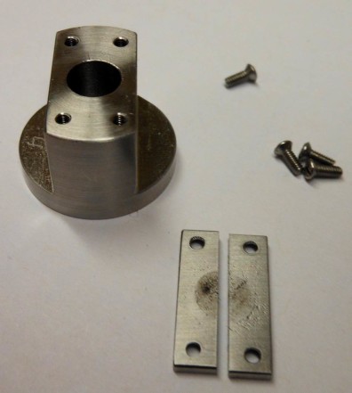
My graduate students misaligned our quadrupole and the TOF when they put the instrument back together. No ion signal was observed. They took the instrument back apart and examined the TOF’s spatial filter. An ion beam that well confined has very little opportunity to scatter.
Scattering can also occur if the ion beam is continuous as it is for any commercial Q-TOF. Ours is not. We trap the ions and then eject them into the TOF in a single plug. The temporal profile of our injected ions is shown in the next figure below.
The temporal width of the ejected singly-charge BSA ion packet is 150 us. The flight time of BSA+ is approximately 1.4 ms. The ion spread at the detector is 2.2 cm. The width of the detector is 4.0 cm. Consequently, every BSA+ ion that we inject into the TOF is detected.
The temporal and spatial focusing of the ion packets injected into the TOF is so well confined that they do not permit ANY ion scattering off the electrodes. This is the reason that there is no scattering based noise in our spectrum while there is from any other Q-TOF mass spectrum.


